Please visit our home site at www.TRILOBOATS.com.

Anke and I live aboard WAYWARD, and wrote about it's design and construction at ABargeInTheMaking.blogspot.com.

Access to the net comes and goes, so I'll be writing in fits and spurts.Please feel free to browse the archives, leave comments where you will and write... I'll respond as I can.

Fair winds!

Dave and Anke
triloboats swirly gmail daughter com

Showing posts with label Barge/Scow. Show all posts

Monday, April 13, 2026

Guest Post: MARY H by Chris George


MARY H
All photos supplied by Chris George


Lord, it was day and night and night an day work when in season!

- Some Old Salt


MARY H
  Guest Post by Chris George

In 2022 Massachusetts announced a small business grant for Green Innovation and Climate Resiliency in the commercial seafood sector. I won the grant and built a scow for my shellfish farm. Having read the Triloboat Blog for years, I had formed the idea that a sailing scow could be useful. The book Trade Winds by Christiaan de Beukelaer implanted the idea of using sail, and maybe electric, to power my work on the farm for climate reasons. The idea was born and I received $25,000 to build and work the boat. She is named the MARY H, after my wife, and her mission is to carry and deploy aquaculture gear and pick up oyster and quahog seed and drop off harvests to a hatchery facility about one mile away across part of Cape Cod Bay.

The design already existed in Howard I. Chapelle’s classic American Small Sailing Craft as the Cape Cod Bay Pound-Net Scow. In the old sailing days, these boats mainly fished herring - and fished the species out! They look like the TRILOBOAT StudyPLAN SANDBOX, but evolved slightly curved sheer lines helping with the “roll to the sea, as there often is on the Cape shore” and historically carried a pile driver. I sent to the office of ship plans at the Smithsonian and for $60 they sent me a tube full of diagrams of old scows -including Great Lakes types - along with Chapelle’s lines, taken off in Provincetown in the 1940s. To start I had Dave’s blog, Chapelle’s book and an awesome picture I found on the internet of a model built locally off the same plan, credit Rob Napier. 

The original boat in the plan is 36’ and I determined for the scope of the project, and town mooring regulations, to scale the build to 20’ - though I did wonder if proportions would get weird later on. So off this poster-sized plan I made a table in my notebook with an engineering ruler and scaled all the points of measurement for 20’. I also set about making an 8’ mock up with a couple scrap veneer plywood sheets and a cardboard model. Making the model was fun just tracing the plan onto cardboard and adding a chopstick mast and paper sails; at that size my old G.I. Joes look like a person of 5’4’’ height. 

To build the boat I had written some pay into the funding to hire skilled help. I hired a friend of mine, a retired roofer and now bricolage artist with whom I had already worked on a few building projects. The first thing we did was to locate a tree for the mast and let it cure for about a year. It’s a beautiful mast! We found a very straight white pine of about 24’ in the woods on a neighbor’s property. Stripped it with a machete (held like a spoke shave) and then coated it with wood preservative and hung it in my garage. 

Severely squeezed into my garage, the actual assembly and building went straight down the lines of “Instant Boats.” Dynamite Payson virtually dictated the techniques that I would modify. Cutting out the main pieces from plywood was most of the early work. I referred to the notebook table a lot and because the math was simpler to convert inches in decimal (remember the engineering ruler), I made sure to make an extra column for the conversion back to 1/16th inches for my measurements on plywood, transcribing the height of the sheer above bottom. The one caveat is that this measurement required another column in the table because the Pythagorean theorem had to be applied to account for the flare of the hull as the Chapelle plan just shows a profile view. No lofting though! A Kreg brand T-square was used constantly. I made a useful misstep while building the mockup that helped me realize to account for flare because I paid a printer to just proportionally enlarge the plan and I used it like a template. When assembling the mockup (which I may still employ as a standup paddleboard) using stitch and glue with zip ties, it felt scrunched down. This effect was not noticeable at the tiny size of the model. The actual cross section of MARY H is 5’ across the bottom with a 5’6’’ beam on deck. 


The winter months were spent in the garage with a space heater cutting and edge joining the plywood with epoxy and fiberglass. The gunwales were constructed in this way as well as five transverse bulkheads for holding the structure together like a ladder. Striking the fair curve of the bow and stern were the most ancient and nautical feeling part of the process. It was accomplished by laying the measurements on the plywood with nails and bending a piece of PVC edging around them. The curve was hand cut by eye with a buzz saw through the skill of my roofer friend. 


Building a boat was a lot to ask of my family, three children and one an infant. I did a lot of work after bedtime into the night and tried to involve the children as much as possible. One problem spot occurred while attaching the bottom to the sides for tape and glue. We decided to attach the bottom with the boat upright, bending the kerfed bow and stern up with shims and two-by-fours at both ends. The shape of the boat would be held in place for gluing with bar clamps and screws edgewise above the waterline. The deadflat was easy enough and all joints were bonded with epoxy fillets and fiberglass strips. But the ends had to be done in one fell swoop laboriously levering up the ends of the boat like flaps over the piles of shims while running around to make everything even as sealant set between the seams. We went way over time and things were starting to fail as my wife pulled in with all the kids. Seeing them all it was such a sacrifice not to be able to care for my baby at that time. But I left it in the care of my friend and somehow he finished the bottom single handedly. 

With the hull still upright I built the centerboard box up out of clear pine boards and more marine plywood, splurging on bronze screws. Now looking boatlike, I got a group of friends together to help flip the hull over onto its transoms for sheathing the bottom. All were promised fresh clams or oysters. I sheathed the entire hull on the outside only with one layer of thick fiberglass cloth bedded in epoxy. Once painted the same crew helped me flip the boat again onto a trailer which I picked up reasonably from the USACOE via the GSA, a good resource. The garage doors were popped off the hinges and the boat was carried out by hand. I had lined the trailer with an old foam mattress that I saved for this purpose so she would have a soft landing onto the rollers. 


Outside in the Spring I built deck stringers out of clear pine strapping and built the mast step of extra fir from the skeg. The boat was filled with 100 empty soda bottles for buoyancy with some sealed plastic water cooler carboys for good measure. The deck was cut from the same ½’’ marine plywood as the rest of the boat and laid as efficiently as I could manage. Between every seam I shot marine sealant or sometimes silicone caulk. A somewhat big mistake was not better sheathing the deck somehow because it leaks during rains. It has to be pumped out after rain and storms now while on the mooring. The hull is tight however so the water inside is “fresh.” One splurge was for EVA foam faux wood decking. Rolls of this stuff were moderately expensive but are a big facet of the historical look, and napably soft. Many people have stopped by the boat and remarked they thought these were actual planks. Rub rails are made of super cheap highly sacrificial lengths of furring strip.


Rigging is piecemeal. I got about 100’ each of tan synthetic rope for the halyards and great thick faux hemp nylon rope for the main sheet, also a historical touch. I made a forestay with hardware store steel wire and shackles. Chafing gear is cut garden hose. The sail was made at a sailmaker in Falmouth, Massachusetts. The proportions are kind of weird as the boom is a real deck sweeper. It will help to reef when I sail the boat more in earnest. At this point she sailed down wind, in the lightest winds three times in the Summer and Fall of 2025. Yet, when I put the sail up, down wind, in the lightest wind, it is still hard to deny we are under sail. And that feels great! I am looking at a potentially life long learning curve so there is plenty of time to perfect it. For electric propulsion she hangs two five horsepower German Torqeedo engines off the stern with some Chinese ePropulsion stick engines for backup.

MARY H now sits on the hard waiting for the 2026 season coming up at the end of March. All the people who helped were essential: a landowner letting us search for the mast, friends and relatives who flipped the boat or shot screws or gave friendly advice, authors - I owe them all a ride or at least some oysters. Spiritually, there have been few journeys as rewarding for me as building this boat. At the Christening, the bottle was smashed by the real Mary H.


Expenses

Dave, here. Chris provided his cost accounting under the grant in response to requests in the comment section. His itemized list can be read HERE. Please click on the spreadsheet image for a more legible pop-up.


Monday, October 20, 2025

LUTRA Update: Building Blues and Bloom


A Work in Progress


Rome wasn't built in a day.

-- Old saying


LUTRA Update: Building Blues and Bloom

There are two things I yammer on about:

  1. Small is beautiful.  - E.F. Schumacher
  2. Curves and angles add to building time and effort.  - Me
Yeesh. I should listen to myself.

We're just rounding the one year mark on what we'd estimated to be a four month project. Six months if the stars mis-aligned.

A winter build - now approaching another? -  interrupted work with deep-freezing spells and general hypothermia, leaving us staring stupidly at simple tasks. Weather - exceptionally cool/cold and wet stretched from that winter, through spring to latish July, bringing mildew in its train. A series of guests (whom we thoroughly enjoyed) brought a warm spell that ended promptly with their last departure. Back to hypothermia. Our short-handed community has needs with few to step up. Our own life has chores that can't be indefinitely deferred.

It adds up to a blues riff.

But one step in front of the other. The structure is complete and we're building and tacking on gear (hatches, tabernacles, bow rollers, cleats, rails, rudder/tiller, etc.). In a week or two - barring further issues - we'll start the simple interior, then windows, then launch. we're hoping for 2025.

So we persist. We dream of returning to life at large among the islands.

We bloom.


*****

It's a challenge taking photos from point blank!


Rowing Cockpit from Forward
Longitudinal Seat/Lockers between Self-Bailing Decks
Main Tabernacle at Main Bulkhead


Rowing Cockpit from aft
Longitudinal seat lockers to Leanbank/Fo'c'stle Hatch
Fore and Main Tabernacles visible


Friday, August 30, 2024

Lofting Low


Everything should be made as simple as possible.
But not simpler.

Albert Einstein


Lofting Low

Being naturally lazy, I've spent an inordinate amount of mental energy on making boat-building easier. Over the years, whole swathes of the process have been successfully dumbed-down toward small enough bites for Anke and me to chew. Economical in time, space, money and materials.

One such swathe is is the process of lofting a vessel. 

'Lofting' is laying down the lines which define the shape of the vessel and some its components. All the individual lines need to agree with each other, meaning extensive cross-referencing and nudgings until they do. This is a finicky process, involving patience, focus and good spatial visualization.

Generally, this is done full-size or at some large fraction thereof. The resulting vessel is 3D (three-dimensional), but the lofting is generally laid down in 2D... done on a flat expanse called the lofting floor. Often, it was located in a loft under the roof of the building shed... hence the name.

Still with me?

Okay, let's take a survey of things we need:

  • A lofting space - This is generally in addition to the construction space and preferably stays available throughout the build. The lofting floor should be out-of-the-way, amply sized, smooth, sheltered and hopefully warm.

  • Esoteric skills - Lofting isn't rocket science, but neither is it run-of-the-mill. We need to understand the specification of points and lines as they relate to the plans, the techniques for laying them down, fairing, correcting and coordinating and further techniques for taking them up again to apply to our growing vessel and its parts.

  • Special tools - The more complex the lofting, the more tools we will need. Splines, ducks, tacks, pencils (of various colors?), spiling (taking the pattern of a curved or otherwise complex shape) plus related tools... and so on.

  • Time - A fair amount of it, especially if this is our first rodeo. Especially if the vessel's shape is complex. Especially if the loft itself must be built.

I can't count the number of times I've bemoaned this list, only to have someone tell me how simple and easy it all is. Only problem is that I've done it and it isn't.

Let's see what can be done to ease our way...


Simple Vessels in Sheet Materials

The first step is to simplify the problem.

Sheet materials generally lie flat or follow a section-of-cylinder or section-of-cone. Vessels built from them are a subset of shapes which - as a class - are generally much easier to loft and build.

NOTE: Sheet materials may also be tortured into compound curves but that ain't entirely simple, neither!

Simple vessels with fewer and simpler curves are easier to loft and build. In this post and lead image, I attempt a rough hierarchy of vessel shape complexity.


Lofting Space

Clearly, if we can take the loft out of lofting, we're ahead of the game.

Phil Bolger with Dynamite Payson popularized Instant Boats in their book(s) of the same name. A key feature is that the lines are laid down (lofted) directly on flat panels (e.g., bottoms, sides, decks and components) before bending into shape. Such lines are said to be expanded.

Following this practice, one eliminates the separate lofting floor. Time and potential errors are saved as most lines are directly cut to shape the panels (no transfer from loft to materials).

In our (flat and rockered bottom) builds, we've taken to building the bottom first, in sections which are finished, flipped and joined. While still flat, we use this structure as a building platform for bulkheads, sides and other components. Once ready, we assemble the structure building upwards from the bottom. This saves flipping a vessel that has been built inverted.


Esoteric Skills

By this point, the 3D shape of the vessel has been chosen and designed for low complexity. Required skills are accordingly much reduced. 

Spatial visualization is far less taxed. Cross-references are minimal and straight-forward. Curves are simple and simply faired. Corrections are mostly limited to point control (vs the correction and coordination of interrelated lines).

Design can go a long way toward easing or eliminating spiling. Box-Barge/Scows, for example are self-rectifying (if the edges meet, they pull themselves into square). Their parallel sides and dead-flat bottom sections mean 'house-carpentry' for most of the hull (no spiling at all!).

In TriloBoats, the use of whole and simple fractions of sheets mean laying out and cutting are held to the minimum, with attendant reductions in waste.


Special Tools

While a few special tools will likely be necessary in any hull shape more complex than the simple box, simplifying holds them to a handful.

In particular, simple curves allow stiffer splines that are generally three point curves (two control points - one toward each end - plus one somewhere in the middle. Unlike the more sophisticated tools for fairing complex curves, simple weights over a sharp corner suffice (of a plank, say, or paperback book).

Design can often help here, too - employing simple rectangles and arcs of a circle - to eliminate splines and rolling bevels.


Time

Everything discussed here has saved time. Time, time, time, time.

Lofting space comes 'free' with the vessel being built. This is (infra)structure right at hand (no round-trip to the loft, looking for a clue).

Simpler lines are laid down once with straight edge, simple spline and radius, and rarely 'taken up'. Cuts are made directly along these lines. Spiling is reduced.

At the extreme end (box-barge/scows) much time is saved in layout, cutting and squaring up the hull. Spiling, most bevels and all rolling bevels are reduced or eliminated.

Bolger never liked the term instant boat, but we can sure edge closer!


*****

Nothing I've written here is in disparagement of lofting or the complex end of vessel space. I love those Curvy Dogs! I respect those who lavish their skill, time, energy and passion in every aspect of their construction.

But like I said, I'm lazy. What's more...

I'd rather be sailing!


Friday, October 15, 2021

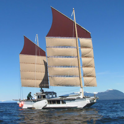
Cat Ketch WAYWARD's Prototype Split Junk Rig


S/V WAYWARD

Photo by John Herschenrider


In theory, theory and practice are the same.

In practice, they are not.

— Benjamin Brewster


It may work in practice;

But does it work in theory??

— Unknown


Cat Ketch WAYWARD's Prototype Split Junk Rig


General Approach


WAYWARD ex T32ft x 8ft x 1.25ft, is our box barge / scow, sailing live-aboard home. My wife, Anke Wagner and I sail engine free, year round in the archipelagos of SE Alaska.


Oh. And we’re lazy sailors.


Our cruising grounds are haunted by williwaws (sudden, fierce, katabatic or downdraft winds that roll off snow and glacier fields), and strong tidal flows that often entail sailing at night. Short, steep seas with plenty of fetch are common, as are swathes of water which can erupt on short notice into ‘dancing water’ riptides. ‘Haystacks’, fortunately, are rare. 


Long, narrow straits and ‘canals’ generally align the wind and seas.  Thus, we are usually sailing directly into it or with it. We find ourselves mostly close-hauled or broad reaching (to comfortably quarter seas).


Ultra-shoal draft, enginelessness and proclivity have us frequently sailing the poorly drawn and often rocky fringes of the chart. In these places, maneuverability and flexibility are much more important than optimal windward ability.


To meet these conditions, we have come to prefer a rather snug, Cat Ketch Junk Rig, ‘dumbed down’ to its bare essentials. 


We like ketch rig for its handiness. Its large sails toward the ends of the hull have several practical advantages:


  • Each sail strongly affects its end of the vessel, both while drawing and backwinded... this lets us turn on a dime in our own length, adjust balance and total CE as we please and sail backwards with ease.

  • Sliding backwards with mizzen backed and rudder reversed, we can reliably come to our chosen tack... this is useful sailing off close quarters anchoring, tacking or drifting (bow on), in about half a boat length, in all winds. Greatly reduces pucker factor!

  • The mizzen can be sheeted close or flat to hold the bow toward or into the wind… this is useful for treading water for a break, maneuvering or allowing traffic to pass.

  • Main sheets are clear of the cockpit and companionway… neither are swept when tacking or jibing.


  • Both masts are clear of the interior… elbowroom, and the bunk to ourselves!

  • The rig is redundant... Should we lose a mast, we can sail under main or mizzen alone (proven by experience), and jury rigging possibilities are much improved.

  • Each mast can be used as a crane for raising / lowering the other… this is very handy for hoisting one’s own petard.

  • Two masts can load cargo or an MOB at either end of the vessel… and we have holds at each end to match.

  • Two masts give a great place to hang a hammock...  8)


For years, we’ve flown flat cut, modified Hassler/McCleod sails. If twist is controlled to allow more in light airs and less in heavier winds, they performed quite reasonably well. We do need to sail somewhat broad on the wind when close hauled in order to sail well.


In our last boat, we reduced the HM upper panels to a single, mostly triangular panel with a deeply hollowed leech, emulating one of the many Polynesian crab-claw styles. 


These flat cut sailforms develop camber from their conic section under press of wind.. 


Pronounced leech hollow brings that panel’s CE (Center of Effort) toward the mast, easing weather helm. As the last sail standing in heavy going, this is an important feature (this will be enhanced by SJR’s greater balance).


Since the two sails enable adjustment of their total CE, there is no need to reposition either. This has a number of simplifying consequences.


  • Standing yard and batten parrels are sufficient to hold and position each sail on its mast. 


  • Our only running lines are one sheet and halyard per sail. 


The benefit is that we eliminate running yard-, luff- and boom hauling parrels, tack and sail downhauls. This significantly reduces handling, and minimizes potential fouling from loops of slack line when reducing sail. 


Sheets are single, aft led running lines of 6 and 5 part. Both are led to the cockpit from forward (we can maintain our forward lookout while handling all lines). Good mechanical advantage means no sheet winches necessary.


We sometimes clip temporary downhauls to batten parrels during heavy winds or special situations. The forward lift is running - to lift the forward end of the sail for visibility or drip control - and tied off on the boom, but is seldom used and may be considered standing for normal use.


In considering SJR and/or cambered rig, we were primarily hoping to improve our performance to windward, while staying within the same profile and priority on handling simplicity.


S/V POPPY

Photo from Slieve McGalliard

JunkRigAssociation.org


Split Junk Rig


Slieve McGalliard developed the Split Junk Rig (SJR).


In his approach, the balance of a junk sail (area forward of the mast) is ‘split’ from the remainder by a vertical gap. Forward are the ‘jibs’, and aft are what I’ll call ‘after panels’.


Upper panels may or may not be split.


All panels are generally cambered for improved aerodynamic lift. Camber is designed with an eye to, “a large entry angle to help produce high lift and a low exit angle to produce low drag” [from C and SJ by Slieve McGalliard]. 


In particular, jib panels are shaped especially full at their leading edges, achievable with the ‘angled shelf method’. 


Additionally, each jib airfoil is shaped with a lofted in sheeting angle relative to battens and after panels. This emulates the set of Bermudan style jibs.


The yard is generally drawn at a low angle, reducing vortex drag near the peak and stresses throughout the rig. The halyard and uppermost batten parrel fixes the upper panels’ position on the mast, letting the lower sail hang vertically.


Handling is limited to halyard, sheet and downhaul adjustment.


An early sketch with ‘vanity panel’ (didn’t make the cut)

 and triangular main heads’l...


Dumbing Down SJR for WAYWARD


We chose to test retaining a) flat cut upper panels (‘crab claws’), and b) a flat cut mizzen. 


Respectively, these likely, and surely detract from SJR and cambered performance enhancements. Yet for our situation, we consider the compromise to be attractive.


Flat Cut Mizzen (vs. Cambered Mizzen)


Flat cut sails are taut across their panels, so transfer stresses vertically along the whole panel, and do not allow diagonal movement. In contrast, cambered sails are slack across their panels, so transfer stress vertically along luff and leech (via roping) and allow diagonal movement.


Flat cut sails on canted battens develop positive batten stagger (upper battens overhang lower battens at their aft ends). Cambered panels have neutral stagger.


Flat cut sails do not flog when slack in the wind. Cambered sails do. When the vessel is tossed from side to side (e.g., when caught in a windless rip tide), cambered sails can ‘pop’ loudly from side to side.


Flat cut sails, when backed, get an immediate ‘bite on the wind’. In cambered sails, we suspected, the forward camber does not engage as soon when backed (later confirmed when backing the main), so require more deflection for a given effect.


In a flat cut mizzen, we value:


  • Extreme ease of construction with very little lofting… large spaces out of the weather are hard to come by and are usually only available for very short windows.

  • Positive batten stagger… this virtually eliminates sheetlet/block fouling. As our mizzen battens end flush with the transom and rather high, this feature is very helpful.

  • No flogging or popping… flogging is hard on the sail, our wa, and interferes with communications between crew. Popping is merely annoying as heck (to be fair, so are all the other aspects of being tossed about; that’s just one more).

  • Quick bite sail backing… small inputs to back mizzen and push the stern to port or starboard simplify and quicken maneuvers, which contributes to safety in tight quarter sailing.


Given where and how we sail, these features are worth quite a bit of enhanced, windward performance. Nevertheless, we prepared to experiment with a shaped mizzen.


All of these considerations apply to the main, as well, but for various reasons don’t weigh in as heavily. Flogging is only briefly tolerated, popping is further from the cockpit, fouling is more safely handled from the deck and backing of the main is seldom necessary.


Flat Cut Upper Panels


WAYWARD’s upper panels (‘crab claws’) raise the yard at a steeper angle than SJR standard. But their flat cut fabric transfers load along their entire run, from the yard to the uppermost batten.  


From There the lower sail (cambered portions) hangs vertically, supported by roping along fore panels’ luff (their leech is not roped) and after panels’ luff and leech.


We hoped, in effect, that yard, panel and batten work together as a very large ‘head board.’ 


As mentioned, the upper panels are the last sail standing. Their amount of camber can be reduced, when strapped down in heavy going, develop low but definite camber while completely avoiding flogging.


NOTE: This can be augmented by a temporary tack downhaul, working against the halyard to flatten the sail. To date, we’ve not felt the need.


Rigging


In most respects, we were able to rig as we have been doing (described above in ‘Background’).


To help top up the aft end of the yard, and encourage the forward swing of the sail, we placed the sling point slightly aft of center. 


Forward movement of the yard is limited by a short, standing yard parrel, which fetches up snug against the aft side of the mast, and runs long on the forward side.


Sail rotation is limited at the uppermost batten by a short, standing batten parrel. It fetches up snug on the aft side of the mast and short but loose ahead. In addition, this limits aft movement of the sail - even when deeply reefed - replacing a running yard hauling parrel.


Once the upper panel is in position, we tie short parrels at each batten. They may be short but loose as there is no apparent batten stagger whatsoever; once the upper panel is positioned correctly, reefing and set are purely vertical affairs. Their sole functions are to keep battens from blowing away from the mast, and as clip points for temporary downhauls.


NOTE: Most analyses of JR sail set focus on limiting sail position via the yard (sling point + yard hauling parrel) and the boom. This still allows the mid sail to rotate forward, which motion is often controlled by luff hauling parrels. It seems to me that limiting rotation at the uppermost batten of the parallelogram (rather than at the boom), controls the ‘high ground’. Everything hangs and mostly behaves below that point.


NOTE: There is a definite but finicky, optimal sling point… too far forward and the yard’s aft end sags; too far aft and the forward end dips below the sail bundle on lowering, presenting a danger to anyone on the foredeck. Look for that Goldilocks point!


NOTE: We had originally thought to hinge the yard and uppermost batten at their forward ends (see drawing, above). Together they would form a strut for better control of upper panel position, and yard dip when lowering. A model looked promising, but we decided to limit the number of new things we were trying at one time, and went with a more standard separation between the two.


Our Theory of Operation of SJR Main and Flat Cut Mizzen


In theory, a flat cut mizzen doesn’t point as high as SJR (or cambered).


This means that, if we point up to the SJR main’s optimum, we’ll pinch the close-hauled mizzen and lose its contribution to overall power. 


Alternatively, we can sail at the mizzen’s optimum and ease the main to match. This swings the main’s force vector forward, improving drive and reducing leeway, without sacrificing mizzen power. In effect, the main will be drawing on a close reach, while the mizzen is drawing close hauled.


Since our pointing was always acceptable to us, improved footing would be pure gravy. 


I’ll note again, however, that we have likely traded away potential performance for what we deem to be flat cut mizzen advantages for our situation.


Prototype Sails


We anticipate a three part main. Upper crab claws, stack o’ jibs and stack o’ after panels, each laced independently in place. But for the prototype...


We built our upper, crab claw panels as final. We laced them to yard and uppermost batten with marline hitches.


Materials are 8ozTopNotch for the upper panels (and eventually, final sails), and 8oz Weathermax. In retrospect, we would like to have made jibs and all lower panels from a lighter nylon, but TopNotch is already purchased and on hand. So it goes.


We increased the proportion of jib to after panels at 1:2 (balance =  33%), adjusted for our deck plan. This further eases sheet loading, and reduces both twist and weather helm when sailing off the wind. I suspect, it increases ‘clean air’ lift and drive from the jibs, as well. 


NOTE: This is in accord with Slieve’s recommendation after having sailed POPPY’s rig at about 1:3 (balance = 25%).


We didn’t anticipate experimenting with the jibs beyond Slieve’s initial specs, so linked them into a vertically contiguous stack of panels (rather than tied and individually adjustable).


The main after panels and mizzen’s panels were built as identical parallelograms (no rounding). 


We lashed the main’s panels Thai-style, but with lashing length varied to induce camber (simulating rounding). We made up a ‘tick board’, marked for distances every foot  from edge-of-cloth to batten for cambers of 4%, 8% and 12% of chord, and began with 8%.


NOTE: 8% camber is a moderate amount which appears to be favored by many offshore cruisers. Many inshore cruisers prefer more. Our inshore cruising seems to have more in common with offshore conditions (SE AK sea and weather conditions, engineless, liveaboard and on the move), so we started there. In particular, we are often tossed in  ‘slop and bobble’ rip-tides, in which cambered sails ‘pop’ annoyingly from one side to the other. 8% has been recommended by several experienced sailors as a tolerable maximum.


NOTE: Lashings were made of three round turns of tarred nylon seine twine, ending with opposing clove hitches around all turns, at cloth’s edge. This let the remainder rotate freely around battens. 


We laced mizzen panels flat and close against the battens. Only if the flat mizzen failed in sea trials did we intend to lash and play with camber options.


NOTE: If they had been available, we would have preferred doubled hook-and-loop strips on a heavy backing, as more quickly and easily adjustable.


Note the wide angular difference between main and mizzen!
Also, that we are still pointing rather high on the wind.


Sea Trials


Questions we hoped to answer in sea trials under prototype included the following: 


  • Is the anticipated gain from shaped sails worthwhile in our situation?

  • Can the flat cut mizzen ‘keep up’ with the SJR main?
    Will it draw at all when close hauled and pointing higher and/or footing faster?

  • Are the amount and distribution of camber too much or too little?

  • Are our dumbed-down rigging arrangements up to the task?


We sailed the prototype for over a year, across a route upwards of 500nm (as the Orca swims… not counting tacks, jibes and side trips). We sailed in estuarial, tight and open waters, flat waters to ‘Chatham chop” to about 15ft swell, against and with the wind from calm to about 55kts (we only tried beating into about 40kts sustained).


Results


Theory panned out!


The ‘head board’ idea seems to have worked out very well. As goes the headsail, so goes the rest.


Sailing ‘close hauled’ (mizzen close hauled; main sheeted high on its close reach; upper panels assuming varying degrees of conic section) we pointed several degrees higher than with both sails cut flat, and footed faster.


We clearly improved our windward performance. 


Off the wind, any gain wasn’t particularly noticable, but no complaints. 


NOTE: We weren't able to replicate the broad reach advantage Slieve reports. Our main luffed well before his when wung out so far. Possibly, this is due to our sheeting arrangement which has not yet been implemented to help eliminate twist? It would mean that, broad reaching, our boom would be oversheeted when the upper sail is drawing well; the lower sail would contribute less drive. At any rate, shaping did no harm, and additional performance with the wind has very low priority for us.


Tacking, including in tight quarters in flukey winds was reliable.


NOTE: Initially, in heavier winds of around 25+kts kicking a short, steep sea, we missed tacks. Turns out that we were strapping the main in a skosh too tight… once we learned to slightly ease the main, tacks became reliable.


Our ghosting was not noticeably affected. Our concern that unfilled, shaped panels would spoil our acceptable ghosting was unfounded. A ghoster, might still be in our future.


The broad set of the main (close reach) preserves a wider margin of effective sailing above our optimal course (i.e., while pinching). In tight quarters, this reduces demands for attention, handling and pucker factor. It’s the difference between sailing toward the upper end of capability, rather than at the upper edge.


NOTE: We could get the same effect with more drive by easing both SJR main and cambered mizzen in tight quarters. But given that we want a flat mizzen for other reasons, this was an unlooked-for gravy point.


The amount of camber (8% of chord) felt about right to us, and we felt no need to reduce camber from bottom to top. It’s ‘popping’ wasn’t too uncomfortable when misbehaving in a toss. It filled out in lighter breeze than the 12% panel, which on the whole felt like diminished returns for our style of sailing.


The only extra handling the SJR main incurred was the occasional clearing of fouled sheets. We didn’t dock the aft end of the lower panel, but plan to in the final sails which should ease fouling.


We sometimes tidy the reefed jibs into the forward lift (if gathered a little off, they can block the forward view under the boom… a better lift lead may fix this).


Conclusions


We’re very pleased with the results.


For our purposes, the SJR main and flat cut mizzen appear to work well enough together for our purposes, significantly improving our windward performance.


Handling remains simple.


Despite what I’ve written about the attractions of a flat cut mizzen, we’re still considering cambering it. Doing so can only further improve performance by empowering our laggard mizzen.


Cambering the mizzen would give us a chance to experiment with a flattening scheme in which brailing lines gather rounding along the battens when drawn up. This would likely be seasonal, set for the blustery months when a flat mizzen is most appreciated


So many possibilities; so little time!


ADDENDUM:


Since writing this, I’ve become aware that there is some concern regarding overbalance in SJR sails with balances nearing the top end of what Slieve McGalliard considers possible (35% of sail chord).


Overbalance, as I understand it, is too much sail area forward of the mast. The overbalanced whole may fail to weathercock (align with the wind) when sheets are let run. A tendency to failure would mean power cannot be reliably dumped in this manner, and rounding up may not be possible.


At 30.5% our SJR balance is nearing that top end, but is not yet extreme?


We can report absolutely no hesitation in weathercocking when sheets were let run beyond normal friction from the blocks. We noticed no difference in sheet responsiveness from our previous (flat cut) main, which had considerably less balance.


Relevant differences between typical SJR and ours include the following:


The higher peaked yard moves the CE of the uppermost panel aft, improving weathercocking.


Our sheets are six part vs. the more usual three, which induces more friction, impeding weathercocking.


Opened by Thai style lashings, our after panels had gaps running along each batten. As their maximum point of camber (and therefore of gap) was 33% of panel chord, I suspect the after sail’s CE was moved aft to some small extent. This would improve weathercocking.